← Motorsport · Case study · Final Design Review

TM02
Nose Cone

A new nose cone that directs airflow around it for the best lap time, through low drag and high downforce. Designed from a research base, a scripted LD-Haack curve and iterative CFD.

−31%CFD drag vs. TM01
7.17 N → 4.94 N
−25%CFD lift vs. TM01
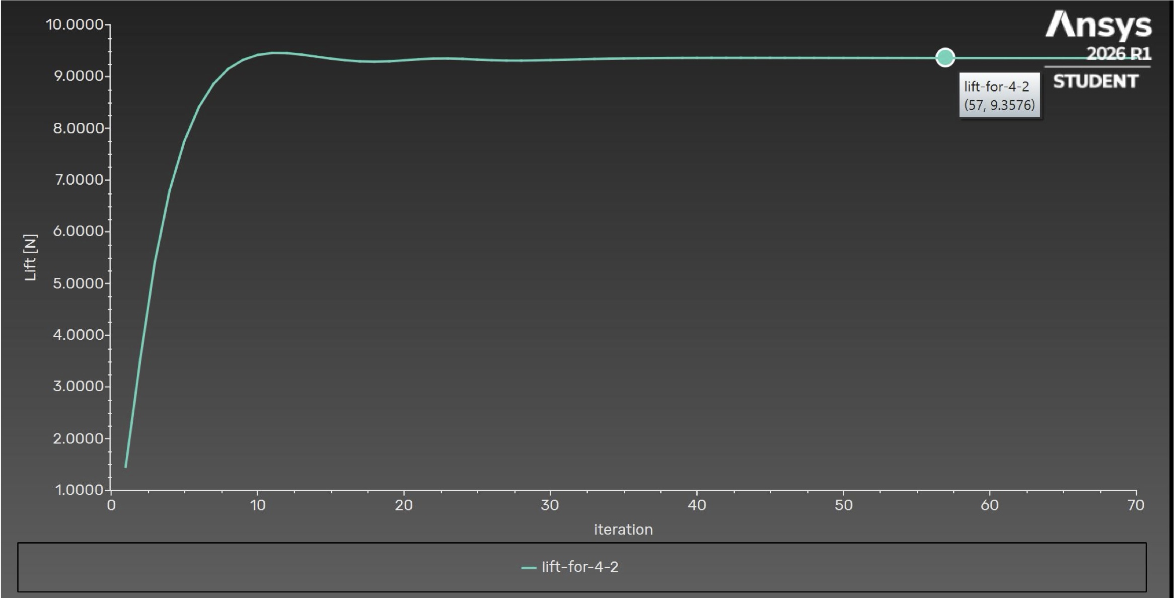
12.40 N → 9.36 N
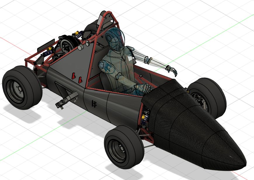
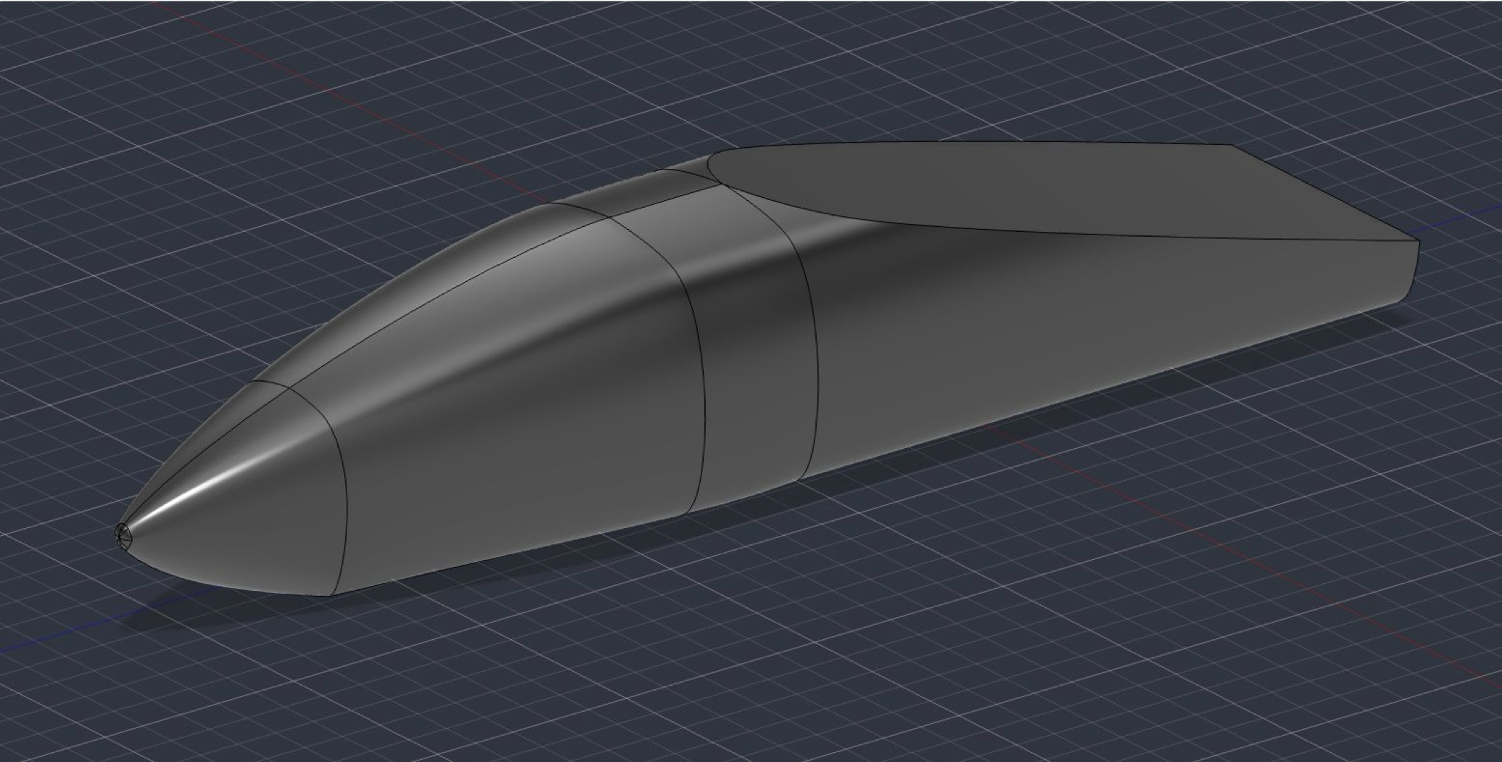
Final CAD model of the TM02 nose cone in Fusion 360

Problem & goals

Problem: a new nose cone that directs airflow around it to give the best lap time, achieved through a low-drag, high-downforce design.

The nose cone has little effect on other subteams, but two are touched. Chassis: geometry affects how it attaches (and the roll hoop design), and downforce adds a small load. Suspension: the extra downforce is small enough to be negligible for ride height.

Improvements over TM01

Kammback in CFD. TM02 simulations include one on the end of the nose cone to act as the car; TM01's first tests didn't.

More informed CAD. Decisions backed by research and analysis, with large gains (see results).

Deeper understanding. A clearer picture of how geometry changes create the results.

CAD techniques

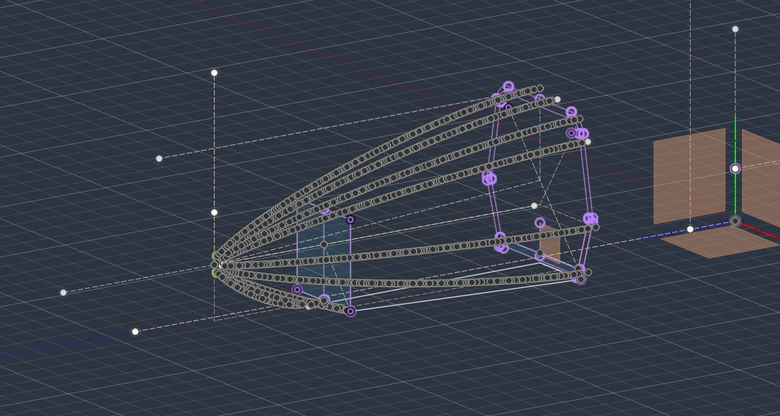
Fusion 360 view of the scripted Haack curve profiles
Scripted curves in Fusion 360.
01

Fusion script for the LD-Haack curve

The curve is defined by (C = 0):

  1. The script calculates the radius at each point along the nose from the formula.
  2. It draws a true 40 mm-radius arc with Fusion's addByCenterStartSweep(), from the tip and sweeping exactly 45° from the centerline.
  3. It finds where the Haack curve's radius equals the arc's endpoint radius (28.28 mm) and offsets the curve so it starts exactly where the arc ends, with no gap.
  4. The arc and spline are mirrored and adjusted to fit the roll hoop dimensions.
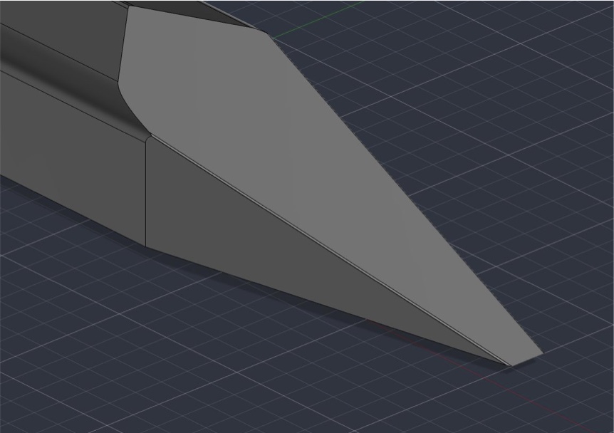
Lofting and ribs

Offset planes and rails build more consistent profiles than rudimentary 3D techniques. The shape is rounder, air spreads more evenly around the sides, and fewer sharp corners improve mesh quality and CFD accuracy. Sketches projected from finished components such as the roll hoop and chassis add precision.

Kamm truncation

A kamm truncation on the back of the model stands in for the rest of the car, so CFD shows more reliably how the nose cone affects the air around it.

CAD of the nose cone with its kamm truncation at the rear
The kamm truncation at the rear of the model.

Final model

Full-car CAD of the Terrier Motorsport car with the black TM02 nose cone fitted on the front
TM02 fitted to the full car, Fusion 360.

LD-Haack cones spread air evenly. Because of the ground, the curve on top extends longer than the bottom, which creates a pressure difference and a slight upward suction force from the changing air velocities. I judged this a worthwhile trade for ease of manufacturing: a smoother, better-crafted nose cone yields better results than a rougher, unevenly curved one. In future models this can be reduced by raising the nose placement.

CFD results

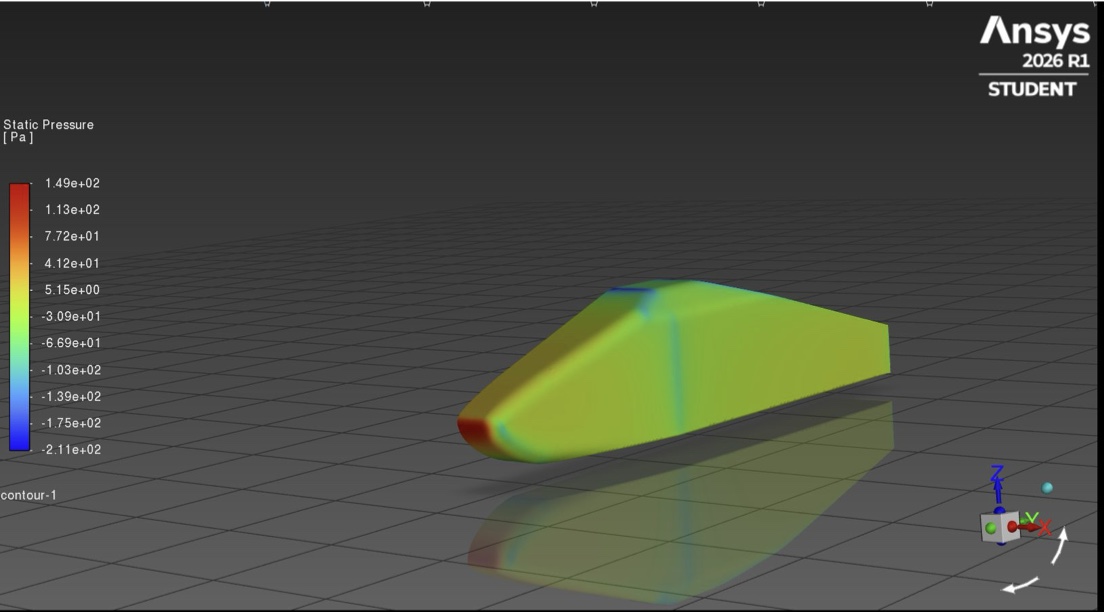
Static pressure contour on the TM01 nose cone
TM01 static pressure (−211 to 149 Pa)
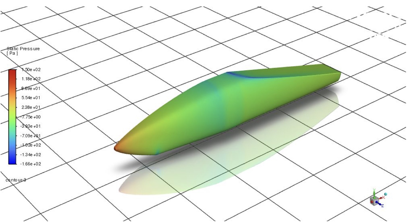
Static pressure contour on the TM02 nose cone
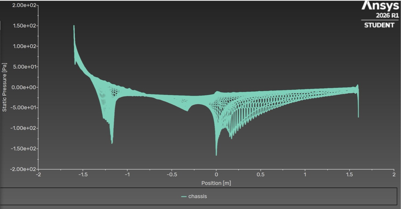
TM02 static pressure (−166 to 150 Pa)
TM01TM02Change
Drag7.17 N4.94 N−31%
Lift12.40 N9.36 N−25%
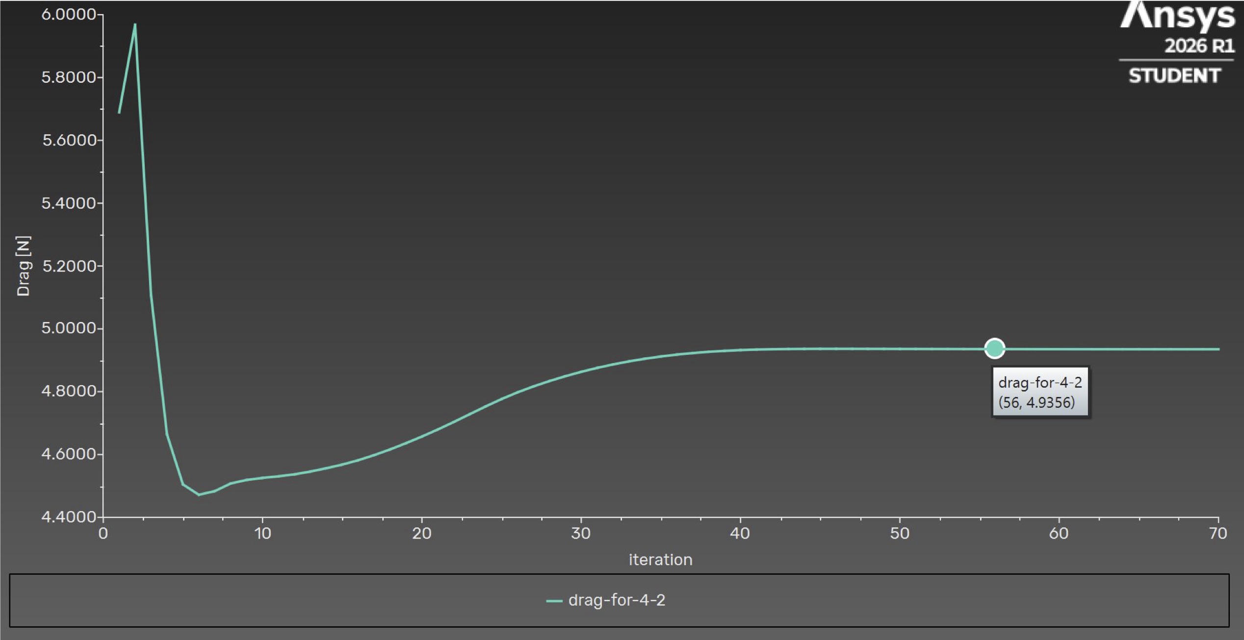
Ansys Fluent plot of TM02 drag converging to 4.94 newtons
TM02 drag converges to 4.9356 N.
Ansys Fluent plot of TM02 lift converging to 9.36 newtons
TM02 lift converges to 9.3576 N.
Static pressure along the TM02 chassis versus position
Static pressure along the nose cone surface.
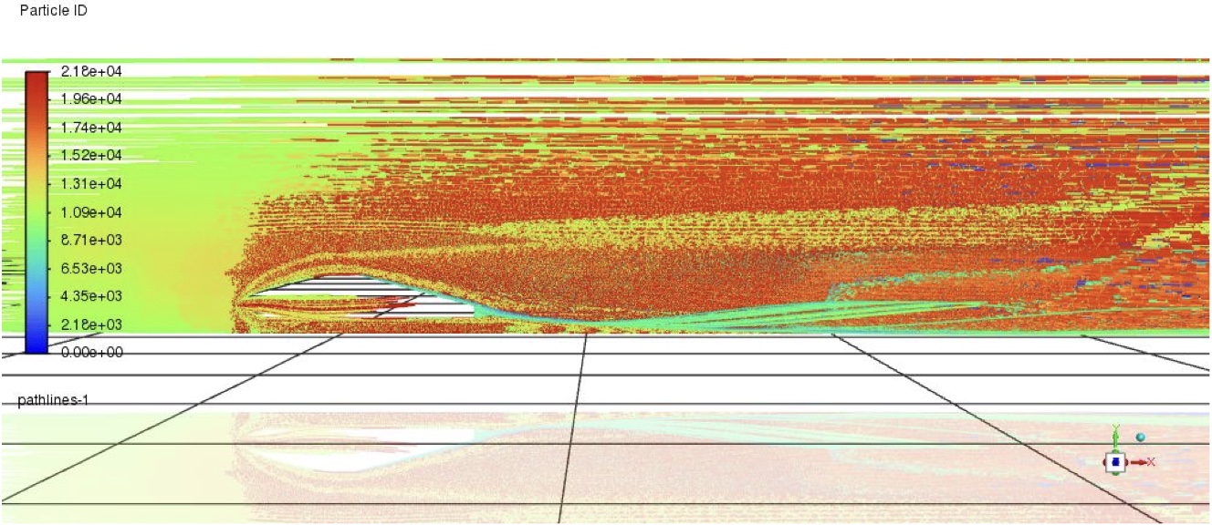
Pathlines of airflow around the TM02 nose cone
Pathlines around the nose cone.

Test validity

657,202Cells
0.976Average orthogonal quality
0.67Max surface skewness
0Skewed cells above 0.70

Manufacturing

Goal: design, document and execute a procedure that gives dimensionally accurate parts, cuts manufacturing time, improves cost efficiency by reducing waste, and reduces component weight.

TM01 assessment

  • Manufactured a fiberglass nose cone
  • Incompatible chemicals and materials
  • High void count in the laminate
  • Excessive waste material
  • Overweight from excessive primer
  • Procedure not documented thoroughly
  • Final part not dimensionally accurate
  • Procedure too laborious (there was only time to build one nose cone)

TM02 plan

  • PLA 3D-printed mold: compatible chemicals and materials
  • Resin infusion or vacuum bagging: fewer laminate voids
  • Lean scaffold pattern: less waste
  • Minimal finishing: no excessive weight
  • Full process documentation
  • 3D-printed pattern, minimal finishing: dimensionally accurate and labor-efficient

Pattern, layup and finishing